
Electrical discharge machining (EDM) has been commercially available for more than 50 years. Today, EDM is used to produce critical parts and components for the aerospace, electronics, and medical industries, to name just a few. The impact of EDM on the die and mold making industry has been especially profound.
In the last 20 years, EDM, particularly ram EDM, has gone through significant changes. Computer numerical control, automation and advanced tooling systems have made unattended operation a reality. At the same time, machine tool builders have made steady progress in terms of speed, finish and surface integrity.
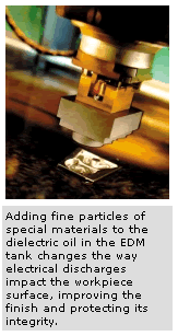
Innovations in additive technology have set a new performance standard for ram EDM once again. Higher than ever levels of surface finish quality are being reached, eliminating the need for benching altogether in some instances. But to understand the role dielectric additives play in achieving these high quality surface finishes, the relationship between the dielectric and the electrodes must be better understood.
How Ram EDM Works
EDM is a method involving electrical discharges between an electrode and a conductive workpiece in a dielectric fluid. Material is removed from the workpiece by a controlled electrical spark generated in the machine’s power supply and discharged between an electrode and workpiece.
 The electrode progressively "erodes" the workpiece, producing a cavity the same contour or shape as the electrode. In fact, making die cavities was such a common application for ram EDM in the early days that it was often called die sinking. The machines are still often referred to as die sinkers. Regardless of the application, the workpiece may be of any material, no matter how hard, as long as it is electrically conductive. However, machining speed will be determined by the material’s melting temperature, as well as its electrical and thermal conductivity.
For EDM, there must always be a small space, known as the spark gap, between the electrode and the workpiece. The gap is filled with a circulating dielectric fluid. On a ram EDM machine, this fluid is usually oil. The dielectric fluid becomes ionized during the course of a discharge. As ionization occurs, positively charged ions strike the workpiece, increasing the temperature at the surface of the workpiece and electrode.
The temperature is so high at the surface, often reaching more than 10,000° C, that it causes the workpiece to melt or vaporize. A bubble of hydrogen gas begins to form. When current flow is turned off, the hydrogen bubble implodes. The force of this implosion forces molten metal to be evacuated from the surface of the workpiece and flushed away by the dielectric fluid. Although most of the molten metal created by the discharge is carried away from the workpiece, a small amount fuses onto the machined surface, creating what is called the "recast layer."
Deeper layers of the workpiece are also thermally affected. These areas make up what is commonly known as the heat affected zone (HAZ).
Copper’s Impact On Ultra Fine Finishes
Fine surface finishes can be achieved with current, conventional EDM technology. The technique involves copper rather than the more commonly used graphite electrode material. Copper lends itself to fine finishes with conventional EDM because it does not have the granular structure of graphite. Copper electrodes can achieve a "mirror" or "glazed" finish (that is, 2µinch Ra) on cavities with a surface area of 2 square inches or smaller.
As the work area becomes larger, however, the finish will deteriorate because a copper electrode cannot easily be contained in the cavity. This is due, in part, to the thermal expansion characteristics of copper. As a result, a fine finish becomes increasingly difficult to achieve as cavity size increases.
Using copper as an electrode material has several other drawbacks.
- Copper, like many other metals, is toxic to living tissue and cannot be expelled from the human body.
- Roughing with copper electrodes is not efficient due to its low melting temperature and expansion characteristics of the material. The maximum amperage that can be applied through a copper electrode is less than 100 amps regardless of electrode size.
- Copper causes oxidation of the dielectric oil. This effect will eventually destroy the dielectric properties of the dielectric, causing slower and slower EDM cycle times
- Copper electrodes often require a deburring operation prior to use in the EDM, adding additional cost and labor to the process.
Finishing With Graphite Electrodes
Graphite is widely accepted as an electrode material in the United States, and it is gaining more acceptance world-wide due to its superior properties. Graphite has a high vapor point (6,000°C), which allows high-amperage roughing. It is easy to machine into a complex electrode form without a burr. It is light in weight.
Another benefit to using graphite is its thermal stability. Even when exposed to extreme temperatures, graphite will not grow. Unlike copper electrode materials, graphite can accommodate up to 600 amps (that is, 50 amps per square inch), producing a very high material removal rate.
However, graphite has a definite grain structure. Some grades of graphite have larger or smaller grains than other. The grain structure of an electrode material is the primary reason that fine finishes cannot be achieved with conventional EDM processes. Conventional EDM processes can achieve surface finishes ranging from 5–10 µm Rmax (35–70 µinch). Keep in mind that surface finish is compared by calculating the microscopic peaks and valleys that are along the surface (for example, 10 µm Rmax would yield a 10 micron height). An enlarged cross section of a workpiece surface reveals these characteristic peaks and valleys. For reference, "µm Rmax" represents the maximum roughness between the highest peak and deepest valley. To calculate an approximate µinch equivalent, multiply the µm Rmax number by 6.7.
Producing finishes better than a 4 µm Rmax with graphite is not economical because burn times become excessive and grades of fine-grained graphite are costly. The best graphite materials have an average particle size of 1 micron (0.000040") or smaller. Graphite electrodes having an average particle size greater than one micron do not have the ability to achieve ultra-fine finishes with conventional EDM.
Here’s why: In EDM, the spark gap controls the process’s ability to achieve a good finish. At some point, the grain size of the graphite interferes with the machine’s ability to maintain the appropriate spark gap. For example, a fine grade graphite such as Poco EDM-3 has grains with an average size of five microns (0.0002 inch). Assuming that this is the average size of all the grains in an electrode sample, the maximum grain size could be as large as eight microns (0.00032 inch).
To achieve a 5 µm Rmax finish, the spark gap between the electrode and the workpiece would need to be at least 15 micron (0.0006 inch). A spark gap of this distance can be maintained because the 8 micron (0.00032 inch) graphite granule released during EDMing can travel through the gap at all times.
To get an even finer finish, less energy must be applied through a smaller spark gap. In other words, the electrode must get closer to the workpiece. A spark gap of approximately 10 microns (0.0004 inch) is necessary in order to achieve a 4 µm Rmax finish. In this case, the graphite electrode and workpiece will probably "short out" because the particles are the same size as the spark gap. The particle creates a short circuit, so to speak, and sparks will not form. Proper gap distance can no longer be maintained, and the burn becomes very unstable. As a result, even on a small cavity, a graphite electrode cannot produce a 4 µm Rmax surface finish using the conventional EDM process.
Large Electrodes Impact Results
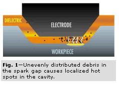 As previously discussed, there is a direct correlation between the size of the electrode and the surface finish that can be achieved, regardless of electrode material. This is due in part to a tendency for particles to concentrate in localized areas of the gap (Figure 1, right). This tendency increases with electrode size. Also contributing is the difficulty in evacuating chips from the gap with larger electrodes.
Hard spots and pitting on the workpiece are formed as the result of sparks firing through large areas of concentrated chips and focussing all of the energy into a localized spot on the workpiece. Another problem associated with maintaining gap stability is the increased electrical resistance that occurs with increased mass. For these reasons, the gap becomes more difficult to control.
Additive Technology
Powder-based technologies have been around for about 30 years. They were initially developed not for fine finishes, but to make the EDM process more efficient. Additives can enhance the EDM process, but like copper electrodes, there are limitations.
All additives provide some benefits for fine finish EDMing, but accuracy, cost and performance vary. For example, chrome has been used as an additive but has high resistance to electrical energy. Chrome particles are large, making its resistance to the flow of energy a disadvantage to machining speed. For this reason, a much slower burn is produced when chrome is used as an additive in the dielectric oil.
Chrome and silicon may also contribute to gap instability. Their heavier weight causes them to sink in the cavity. Constant movement of the fluid is essential to keep them suspended and prevent them from settling. As the cavity becomes deeper, the bottom may finish properly. However, because of settling of the additive, finishing of the sidewalls becomes more problematic.
Silicon, chrome and other powder additives are still used in dielectric oil. However, these additives are expensive, difficult to dispose of and may be considered toxic heavy metals.
In addition, "surface agents" and other chemicals may be required to prevent the particles from forming clumps, which are naturally unstable. For example, chrome particles have a tendency to stick to each other, thus requiring a surface agent. The surface agent may be toxic, too.
Some additives create the appearance of a superior finish by plating or pooling material on the EDMed surface. The re-cast layer may look right, but there are problems just beneath the surface.
Some additives require the use of two dielectric systems, one for roughing and another with the dielectric additive for finishing. This may impede unattended operation or interfere with automation. Once a cavity is finished, the dielectric must be removed and "all" the additive should be cleaned and removed. Otherwise, highly intensified and erratic sparks may cause uneven surface finishes. Maintaining two systems is time consuming and labor intensive.
EDM Or DDM?
"Diffused Discharge Machining" (DDM) technology is another option for EDM finishing that relies on additive technology. This process minimizes the effects of "secondary discharging" and breaks the spark up into multiple sparks through a conductive medium in order to produce superior finishes in dramatically less time. It increases pulse frequency at the lowest output levels by as many as five times. This technique also improves the frequency of discharges when machining large areas, where "chip" build-up has traditionally made consistency a problem.
An example of diffused discharge machining is Makino’s HQSF (High Quality Surface Finish), which utilizes a patented conductive powder the company has named "µSC." This powder is mixed into the dielectric fluid. When the spark gap is controlled consistently and this additive is distributed evenly between the electrode and workpiece, spark frequency improves because there is a more conductive channel allowing the smallest sparks to fire evenly.
DDM technology reduces the loss of power associated with re-machining of chips or "secondary discharging" experienced in conventional EDM technology. A 30 percent improvement in machining performance may be realized. Not only is the surface finish improved, but the HAZ is substantially reduced, improving the integrity of the surface.
The biggest benefit is that graphite can produce finishes previously associated only with metallic electrodes. For example, it is possible to achieve ultra-fine finishes (down to 10 or 12 µinch) using a high-quality graphite, without the need for secondary operations such as polishing. The quality of the side-wall finish also improves because µSC additive used by Makino will not sink or settle readily.
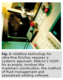 However, this process relies on more than an additive. Special filtration, control software and other enhancements are required. Makino’s HQSF, for example, requires specialized orbiting software, machine construction and fluid management systems in order to provide ultra fine finishes on EDMed parts (Figure 2, at left).
For example, the dielectric management system must be structured very differently from a conventional dielectric system. Orbit control and fluid management software is enhanced in order to achieve finishes without consuming the additive unnecessarily.
The dielectric must be controlled tightly so that the additive remains suspended and is evenly distributed in the gap. Likewise, conventional filtration would consume the additive, impacting operating costs. Therefore, a magnetic chip separator is employed to remove ferrous debris but leave the additive in the fluid.
Traditional EDM seeks the lowest possible viscosity in a dielectric oil in order to improve flushing and to drop "chips" out of the cut. When using additives, on the other hand, the particles must be evenly distributed in the gap. For this reason, the oil must be reformulated with higher viscosity but with the same dielectric properties as dielectrics used in conventional EDMing. Mineral seal oils are not recommended.
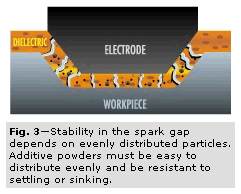 Additive particles with a lower specific gravity than others make suspension in the dielectric oil simpler, resulting in even distribution throughout a cavity (Figure 3, at right). This characteristic provides excellent sidewall finishes, even in deep cavities.
Because the powder has negligible specific gravity and can be controlled easily, both roughing and finishing can be done with a single dielectric system, thereby eliminating the need for two separate dielectric systems. A cleanup between roughing and finishing is eliminated.
In most hardened tool steels such as H13, 420 stainless, S17 and others, DDM provides a potential increase in EDM speed of 20 to 30 percent, depending on the depth of cavity and complexity of the shape. This increase in speed is due to the elimination of counterproductive secondary discharging.
Makino’s µSC additive doesn’t bind to itself, eliminating the need for surface agents. Energy always passes through the most conductive particulate in the spark gap, which invariably is the µSC additive.
Since µSC has a very low specific gravity, orbital motion is enough to keep the additive moving and evenly distributed. Compared to additives with a higher specific gravity, this additive helps maintain accuracy and allows a smaller gap spacing.
The µSC particulate size is 0.0002 inch. To get a 3 µm Rmax finish, the electrode has to be within 0.0003 inch of the workpiece. That gap is too narrow to allow the 0.0004 inch granule from graphite wear to exit, creating an unstable machining environment. This generates highly unproductive secondary discharging. However, the HQSF process allows energy to be fired through the µSC semi-conductor, since it effectively dissipates the energy to the workpiece. Therefore, the electrode only has to get within 0.0005 inch of the workpiece and 0.0003 inch of the semi-conductor, meaning the 0.0004 inch graphite granule can now exit the cavity gap, resulting in a smooth, continual burn. The result is a very fine finish without excessive burn time.
What About The Heat Affected Zone?
The surface finish left by EDM includes a thermally affected layer of material. Sometimes this heat affected zone (HAZ) is called "recast," but only a small part of the HAZ has recast particles. Recast occurs when material taken to a molten state is not totally released from the workpiece by the flushing action of the dielectric and re-solidifies onto the workpiece surface. Ordinarily, these particles can be removed by simple secondary operations.
What is far more important to surface integrity is the "white layer" located just beneath the recast layer. This material has been taken near the melting point and then cooled very quickly by the dielectric. This martensitic, carbon-enriched portion of the HAZ is highly susceptible to surface cracks. Because this layer becomes hard and brittle, it demands the most attention. It represents the greatest risk to surface integrity and therefore to the life of the mold or die.
Early testing demonstrated that DDM produces a HAZ as much as five times smaller than that produced by standard EDM technology and 10 times smaller than that produced by some additives. This reduction is the result of the diffusion of the spark by the additive acting as a semi-conductor. Apparently, heat does not penetrate as deeply into the workpiece with DDM. Thus, the hardened layer is thinner and consequently requires less polishing to remove. In some cases, polishing can be reduced by as much as 50 percent.
Applications
The DDM process has made significant in roads within the plastic injection molding industry, where surface finish and precision are critical. Small- to medium-sized mold cavities that are difficult to polish are primary candidates for this new technology. Reduced hand polishing means better accuracies and lower costs.
Other industries, such as die-casting and large automotive plastic injection molding have realized surface finish improvements on larger parts. Here, the reduced HAZ greatly extends die life. In die casting especially, any flaws or cracks in the cavity surface are highly susceptible to propagation when exposed to the high temperature of molten metal.
Depending upon the application, conventional EDM technology has limitations of surface finish and integrity. Smaller cavities (under 4 square inches) and ribs EDMed conventionally may require secondary operations such as hand polishing for better mold release and better tool life.
The best finish that can be economically achieved on a large (12 inch by 12 inch) cavity with traditional EDMing is 15µm Rmax. Similarly, a 20-µm Rmax surface finish is the limitation of a 20 inch by 20 inch cavity. With DDM, finishes can be improved by as much as 48 percent. The same 12 by 12 cavity can be machined to an 8-µm Rmax finish, and a 10-µm Rmax finish can be obtained on the 20 by 20 cavity. Some additives can be used during roughing and finishing, improving overall performance of the entire process. By better understanding the relationship between the dielectric additive and the performance of the electrode, you can make a positive impact on your EDMed surface finishes.
Re-posted with permission. Copyright 2000 by Gardner Publications. Click here for more industry news from Modern Machine Shop.