High-speed machining (HSM) was defined theoretically by academics in the 1930s and has been in practice since the late 1980s. How high-speed machining is categorized can vary based on market segments, applications, and materials being machined.. For the purpose of this article, any reference to HSM is for machine tool material removal equipment.
There isn't a static definition for HSM as it has been evolving over the years as machine technologies and tooling chase each other with their limitations. However, HSM generally refers to the use of higher speeds and feeds than conventional machining with lighter chip loads to achieve high metal removal rates.

Requirements for HSM:
• Well balanced, rigid machine tool
• High Acc/Dec axes
• Highspeed, thermally stable spindle
• Effective and adaptive machine control
• Properly selected cutting tools
• High speed, balanced tool and HSK tool holding system
• HSM CAM package
• Benefits of HSM:
• Faster cycle times
• Better finishes
• Less stress on the materials being machined
• Better tool life per part
High Speed Machining in General Machining Job Shops
High-speed machining has continued to evolve in high-mix/low-volume general machining job shops, automotive parts suppliers, and other commercial parts suppliers. In the 1990's,high-speed machining in this market segment was described as cutting parts with spindle speeds over 10,000 RPM which allowed for higher metal removal rates. Today, high-speed machining is more complex with a broader focus on all parts of the cutting process.
Design improvements in machine tools has improved the overall rigidity of the machine structure which decreases vibration during cutting. This allows for even chip load in the cut and a reduction in chatter when more aggressive cutting parameters are used. Also, most modern spindles are direct drive which eliminates gear boxes, improving the dynamics of the spindle. Makino spindles have continued to evolve over the years by delivering exceptional power and torque that make it possible to aggressively remove metal by optimizing horsepower/torque curves.
Some machine tools do not have the axis and spindle rigidity coupled with good spindle power required for high-speed machining like the Makino 1-Series horizontal machine centers. To work around that limitation, a CNC milling method called “trochoidal milling” was developed. Trochoidal milling is a technique for roughing and semi-roughing that takes large axial depths of cut by attacking with many high-speed passes that arc in, cutting a small radial depth of cut with each pass. This generates low radial cutting forces, minimizes vibration, and reduces heat in the cutting zone. This requires a machine control with the processing power to maintain the constantly changing feed rate as the tool moves along its circular path.
Like in many aspects of manufacturing, computing power has enabled gains in high-speed machining. It has resulted in the ability to cut parts faster with higher quality results. Modern CNC controllers are powerful with the ability to maintain a constant feed rate which gives a consistent cutting load. This improves surface finish and tool life while making it possible to reduce cycle times. The ability of powerful controllers to look ahead in a program makes it possible for software to optimize tool paths for speed and accuracy. This is only possible today due to the increase in high-speed program data storage and the faster transmission rates for this data.
Over the last few decades, improvements in machine structure design, spindle technology, and computer hardware/software have advanced high-speed machining capabilities of machine tools making it possible to increase metal removal rates and reduce cycle times.
High Speed Machining in Die/Mold Applications
Several changes have occurred in the last 10 years to be able to better utilize high-speed machining of Molds and Dies. Practices and technology have changed in such a way that new ideas have been created and become mainstream in today's most competitive shops. Some of these ideas are roughing and semi finishing closer to zero stock combined with light and fast cuts when compared to the low and slow mentality of the past.
Starting with tooling enhancements, there has been a lot of development work around coatings. Almost all shops have made the transition into carbide tooling so the next piece to look at is the coating. Coatings enable the cutter to withstand heat, which can allow it to be pushed harder than an uncoated carbide cutter. The first key to successful HSM is that the cutter must be able to take the increased heat generation. From there, the chip created must have enough mass to be able to throw the heat away from the cut via the chip. Many of the top tooling suppliers have coatings that can work successfully in 65 HRc or higher! They continue to test new and innovative blends of coatings in order to further advance tooling limitations in even the most demanding applications.

Another often overlooked technology is the increase in tool accuracy. This relates to both size, form, and flute-to-flute repeatability. Just like in the machining world, cutter grinders and the metrology to check the cutters has improved over time. With better accuracy, it's possible to machine closer to zero and get the true form customers desire. The form of the tool is also crucial. When looking at a ball nose tool, if every point on the radius was the correct size, it would help to ensure the best form is going onto each part being machined, regardless of the contact point of the tool. Flute-to-flute repeatability is one of the keys to successful HSM practices. When pushing tooling to its limits, it's necessary to ensure that each flute is taking the amount of material that's anticipated. If one flute sticks out further than the others, that flute will fail prematurely and the machinist will not get the desired result.
One of the last tooling enhancements is the different tool designs. Yes, an endmill is an endmill. However, by adding more flutes, it can be run faster than previously. Manufacturers are making endmills now with 6, 7, and even 8 flutes! The machinist needs to pay attention to the additional flute designed cutters because some of them have deep flute gullets for softer material while more solid-core tools are specifically designed for harder metals. While this is not a novel idea, the barrel or lens design has begun to show up in increasingly more shops. This large radius tool enables machinists to take larger stepovers but still achieve the same finish as a smaller tool. The result, a much quicker cycle time in the right application. These cycle time reductions can be as high as 6 to 8 times faster or more! The larger cutting radius can also help with cutter life, enabling the machine to run for a longer period with less tool changes and edge breakdown.
These tooling enhancements are all then supported by the machine tool. All machine tool manufacturers talk about machine rigidity, but what does that mean to the machinist? The ability for the machine to resist deflection and deformation when running is crucial. When shops try to run the machine at increased speeds and feeds, the machine will have a lot more acceleration and deacceleration. Additionally, it could be creating more force on parts of the machine tool that need to be stiff and rigid to ensure the cutter is machining where intended. Just like flute-to-flute repeatability from the cutter, if one pass leaves more material than intended, the next pass may have not remove the extra material that the first pass missed.
Again, while this isn't a new idea, the HSK toolholder interface is substantially better when comparing a CAT interface. The increased contact area of the HSK provides a much stiffer and rigid design and can result in better tool life, part accuracy, and an improved surface finish. An 63a HSK interface can withstand 5 times the radial deflection when compared with the equivalent CAT 40 taper! A 100a HSK interface is 7 times stiffer when compared to the equivalent CAT50 size taper. With the advancement of better CNC lathes and grinders, the HSK interface has come down in price enabling more shops to get their hands on these tool holders.
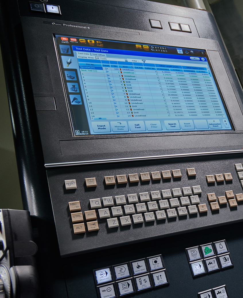
The machine tool's controller will also have a significant effect on HSM. The look-ahead technology must recognize when the machine can accelerate rapidly or if it needs to slow down in a corner in order to make an accurate move like is accomplished in Makino's Pro6 control with SGI.5 adaptive control. Much like a race car drivers' ability to navigate a road course, the controller needs to be aggressive when it can, and navigate slower and more carefully when making tight, accurate turns. Since HSM often calls for light and fast cuts, this look-ahead technology can dramatically slow down a tool path. If the CAM system estimates that a tool path should take 30 minutes, it typically does not include acceleration and deacceleration. The result isa longer cycle time once the part is run on the machine. A high-end machine tool controller will be able to navigate the g code easily and enable the machine tool to complete the toolpath as fast as the machine design allows.
Another major advancement with HSM is spindle load monitoring. Machinists are asked to push the machine and tooling to its limits, but what happens if something goes wrong? It only takes a small mistake to create a huge, costly fix. With spindle load monitoring, the machine will monitor the load on the spindle and can send an alert before any damage occurs. These alarms can be set to monitor excessive HP, torque, or force applied on the spindle and can help save the tooling as well as the spindle in the machine.
This software has also enabled today's modern machinist to be able to think about part processing differently. High end CAM systems, for example, have changed the way many manufacturers rough their parts. Trochoidal milling is very popular and involves milling with the side flutes of an endmill and a larger depth of cut, but a shallow stepover. The metal removal rate can be huge when the part allows for this type of tool path to be used rather than the conventional Z slice method. Additionally, software companies have enhanced this tool path design to look more like a “D” when cutting as compared to an “O.” This simple reduction in length creates a faster cycle time. Even better, when the cutter is not engaged, it's possible to add lifts in the Z axis, so the tool is not dragging over material that has already been cut. This reduces the amount of heat generated on the tool.
With these enhancements to toolpaths, the computer must be able to handle the increased requirements. If it takes hours to generate a tool path, would a new or different designed computer be able to do the same in a few minutes? Its common knowledge that computers are updated almost every year with new technologies and CAM systems have begun to take note of this. Processing tool paths in the background enables the programmer to continue to work while the tool path is generated in the background. Further, newer computer processors have more cores which allow modern CAM software to do more calculations simultaneously, resulting in quicker tool path generation.
It seems like nearly everything about HSM has changed over the last 10 years. While the theory and some of the ideas remain constant, the application continues to be propelled forward. Whether it be a better tool coating, a more rigid machine design, or a new way to tool path concept, the ability to combine the best practices is what enables todays modern Die/Mold shop to run HSM.
Today's 5-flute high-feed roughing end mills achieve 4X higher MRR (Material Removal Rate) in P20 tool steel.
High-Speed Machining in Aerospace Applications
High-speed cutting techniques have been common within the Aerospace industry for very many years. Initially, these techniques were applied to aluminum parts; however, over time the same types of cutting approaches have been applied to other aerospace materials as well. “Go fast and take a light cut” applies to all these materials, the difference being what constitutes “fast.” Fast in titanium is dog slow in aluminum.
The development of high-speed machining has always been a “leap frog” series of product/process improvements between the machine tool builders and the cutting tool suppliers. As higher performance spindles became available, the cutting tool performance was often the limitation. As cutting tools improved, the spindle speed and power needs increased, causing new machine and spindle designs to become available. This sequence continues.
Today, Makino offers large, high-performance aluminum-focused machines with 33,000 rpm, 175 horsepower spindles and large titanium/hard-metal-focused machines with 4,000 rpm, 130 HP, 737 ft/lb spindles.
Smaller machine platforms may also be configured to provide high-speed machining capabilities for smaller parts.
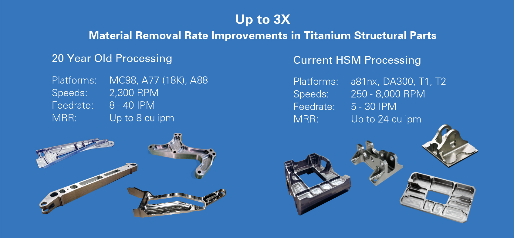
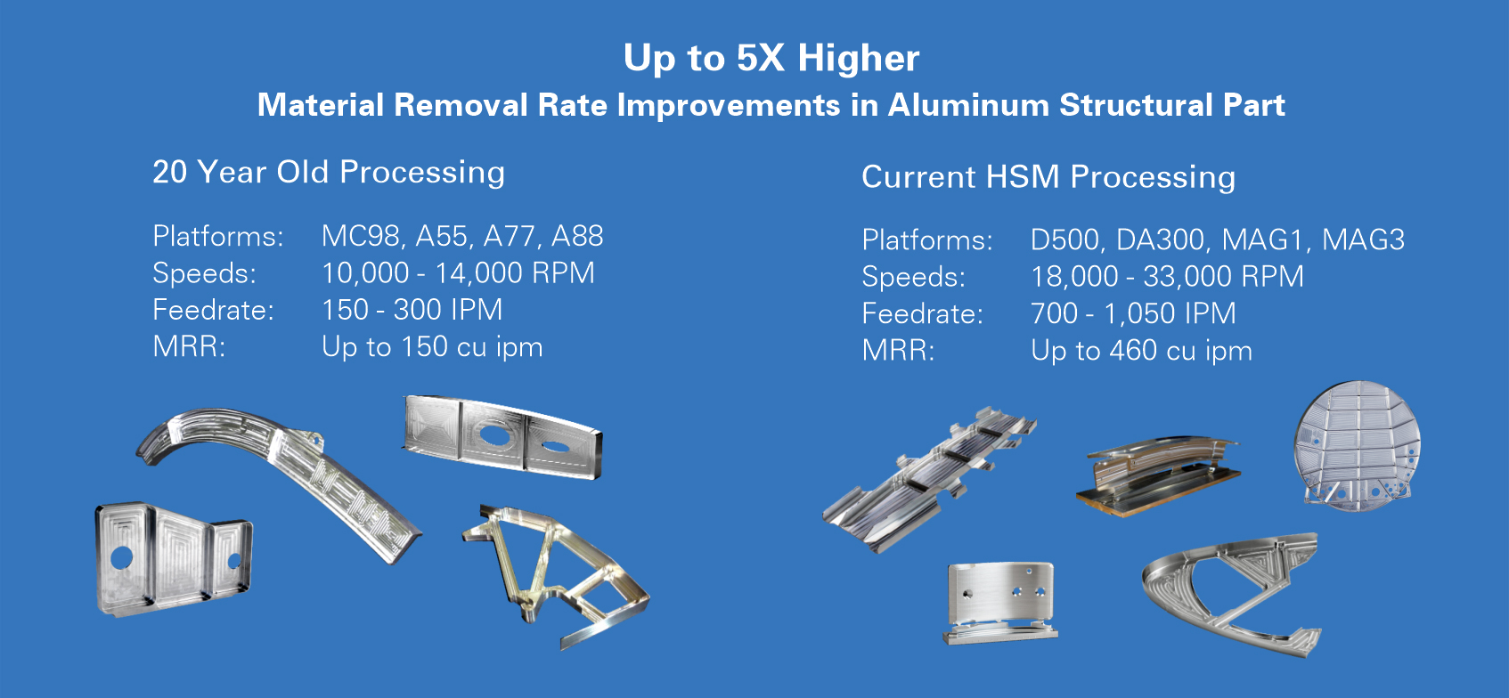
Current process performance parameters as well as what was considered high speed aerospace processing 20 years ago are shown in the following examples:
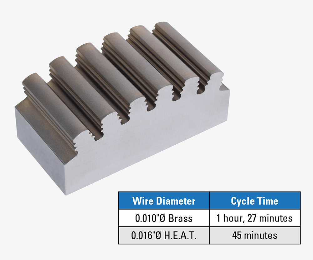
Example of a fir tree slot on a turbine disc being machined on a Makino HEAT Extreme Wire EDM at a 48% reduction in cycle time due to 1.9X faster machining speed.
While searching for machine tools to adopt HSM, look for demonstrations of rigidity, adaptive control processing speed and spindles that can run at unlimited full duty speed. It takes more than just the machine tool—all the other aspects like tooling, toolholders and CAM systems are designed to work together for HSM.
In summary, HSM takes many forms dependent on materials and applications. While it's the standard for today's machining, it's dynamic and will change as technologies are developed.